
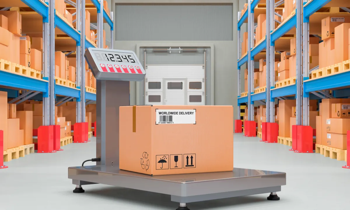
An industrial floor scale may appear properly installed yet still show a different weight when the same pallet is moved from the centre to a corner. This problem can disrupt stock records, production reports, dispatch documents and commercial transactions. Recalibrating the indicator may improve the reading for a short time, but the error often returns because the real cause is mechanical rather than electronic. The problem begins with the way force moves through the scale. The applied weight must pass through the weighing deck, structural frame, load-cell mounts and load cells before reaching the foundation. If one support point is higher, a ramp touches the deck, the frame twists or debris becomes trapped beneath the platform, the load cells will no longer share the force correctly. One cell may carry too much weight while another carries too little.
Proper load distribution in an industrial floor scale means transferring the applied weight into the load cells without unwanted contact, leverage, twisting or side force. A stable foundation, correct load-cell alignment, full support at every mounting point and a successful corner-load test are therefore essential. These conditions allow the scale to produce consistent readings across the platform instead of being accurate at only one position.
How Does Load Distribution Work in an Industrial Floor Scale?
Load distribution describes how the weight placed on the scale is shared between its support points and load cells. It is affected by the position of the load, its centre of gravity, the size of its contact points, and the condition of the scale installation. Understanding this process makes it easier to identify why a floor scale develops corner errors or unstable readings.
The Load Path Through a Multi-Load-Cell Scale
A typical industrial floor scale uses a steel weighing deck supported by a structural frame. Many models use four shear-beam load cells, one near each corner, together with adjustable support feet and a junction box. The junction box combines the output from the individual load cells and sends the final signal to the weighing indicator.
The normal load path is:
Pallet or product → weighing deck → structural frame → load-cell mounts → load cells → support feet → foundation
Every part of this path must remain stable. The weighing deck must resist excessive bending, the frame must not twist and each support foot must remain in firm contact with the floor. If the deck touches a ramp, pit wall or nearby structure, part of the weight may bypass the load cells. The displayed reading may then be lower, unstable or dependent on where the load is positioned.
Load cells also need force to enter in the direction intended by their design. Side forces, non-central loading, torsional loads and bending moments can change the measurement or increase stress on the sensor. Load-cell support structures should be level and stiff enough to prevent unequal movement between support points.
Distributed, Concentrated, Eccentric and Dynamic Loads
Understanding the types of load cells is essential for South African businesses
A distributed load spreads its weight across a large area of the weighing platform. A wide container with a flat base is a common example. This type of load is generally easier for the deck to support because the force is shared across several structural members.
A concentrated load transfers weight through small contact points. Pallet feet, storage-bin legs, steel stillages and trolley wheels can create concentrated loads. A pallet may weigh less than the scale’s total capacity but still place high local force on one part of the platform.
An eccentric load has its centre of gravity away from the geometric centre of the platform. This may happen when a pallet is loaded heavily on one side, a drum is placed near an edge or an irregular machine component is weighed. A properly installed multi-cell floor scale should still provide an acceptable reading within its approved operating limits, but the load cells will not carry equal force under an eccentric load.
A dynamic load is created by movement or impact. Forklifts and pallet jacks can introduce additional force as their wheels enter a ramp, cross the deck or stop suddenly. The temporary force at one corner can be much higher than the static weight of the pallet alone.
Why Total Scale Capacity Is Not the Complete Answer
Scale capacity indicates the maximum load the complete weighing system is rated to measure under its stated conditions. It does not mean every part of the platform can safely receive the full capacity as a concentrated point load. Dividing the total weight by four can provide a basic estimate for a centred, static load on an ideal four-cell system:
Average estimated load per cell = total supported load ÷ number of load cells
This calculation should not be treated as the actual load carried by each cell. The real force depends on the load’s centre of gravity, platform geometry, contact points, frame stiffness and movement during loading. If a pallet weighing 2,000 kg is placed heavily to one side, the nearest cells may carry far more than the 500 kg average suggested by simple division.
The scale selection process should therefore consider:
- Maximum normal operating load
- Possible overloads
- Pallet or container dimensions
- Position of pallet feet or wheels
- Centre-of-gravity location
- Forklift or pallet-jack access
- Frequency of loading
- Impact during entry
- Indoor, outdoor or washdown conditions
Scales4U supplies industrial platform scales and several load-cell designs for warehouse, production and commercial weighing applications. Matching the platform size, capacity and load-cell arrangement to the real load pattern is an important first step in preventing installation-related errors.
What Happens When the Load Is Not Shared Correctly?
Poor load distribution may produce several symptoms at the same time. A scale can have a corner error, slow zero return and unstable readings because all three problems come from the same physical contact or alignment fault. Electronic adjustment should therefore follow a mechanical inspection rather than replace it.
Corner and Position Errors
A corner error occurs when the same test load produces different indications at different positions on the platform. The scale might read correctly in the centre but show a higher or lower value near one corner. The error may also change when a pallet is rotated because the load’s centre of gravity moves to a different part of the deck.
Common signs include:
- One corner consistently reads high.
- One corner consistently reads low.
- The reading changes when the load moves across the deck.
- A pallet produces a different result after being rotated.
- The scale passes a centre test but fails an eccentric-load test.
- Repeated corner trimming does not remain stable.
Small output differences between load cells may be corrected through junction-box trimming, but large or recurring corner errors often indicate uneven support, frame distortion, mechanical contact or a damaged cell.
Poor Repeatability and Zero Return
Repeatability describes whether the scale produces the same reading when the same load is applied several times under the same conditions. A scale with poor load distribution may give a slightly different result each time because the frame settles differently, a support foot moves or the deck makes intermittent contact with another structure.
Zero-return problems occur when the scale does not return to its original zero after unloading. The display may remain above or below zero, drift slowly or change when someone walks near the platform. Possible mechanical causes include:
- Debris beneath the deck
- Cable tension
- Ramp contact
- Platform rubbing against a pit wall
- A loose support foot
- A damaged mounting assembly
- Frame twist
- Foundation movement
Electrical interference and moisture can also cause unstable readings, so the mechanical and electrical systems should both be checked before a final diagnosis is made.
Errors That Increase With Load
Some floor scales appear accurate under a light test load but develop larger errors as the applied weight increases. This does not automatically mean the load cells have become non-linear. The structure may be bending, one support may be sinking or an overload stop may begin touching the frame as the deck deflects.
Load-dependent error may be caused by:
- Platform deflection
- Inadequate frame stiffness
- Foundation movement
- Changing ramp contact
- One load cell reaching overload
- Loose mounting hardware
- Excessive concentrated loading
- A support foot losing full contact
The scale should be tested at several load levels and positions. If the error changes sharply at a particular weight, the technician should look for a contact point or structural movement that begins only after the platform deflects.
Premature Load-Cell Damage
A load cell that sits higher than the others may carry a larger share of every load placed on the scale. Repeated local overloading can cause zero shift, output instability, fatigue or permanent deformation. The cell may eventually fail even though the total load placed on the scale never exceeded the stated platform capacity. Incorrect alignment can also introduce side forces and bending moments. Load-cell manufacturers recommend central force application and level, load-bearing support because non-axial forces can affect measurement behaviour and mechanical life.
How to Achieve Balanced Load Distribution During Installation
Balanced load distribution begins before the scale is placed on the floor. The installer must understand the expected loads, inspect the foundation and follow the instructions for the exact scale model. Universal figures for slab thickness, bolt torque, shimming or level tolerance should not be applied to every installation.
Confirm That the Scale Matches the Application
A floor scale should be selected according to the actual material-handling process rather than capacity alone. The installer or supplier should know how the load will enter the platform, where its contact points will sit and whether the scale will face moisture, vibration or frequent impact.
Before installation, record:
- Platform dimensions
- Scale capacity and division size
- Typical and maximum load
- Load footprint
- Loading direction
- Pallet dimensions
- Forklift or pallet-jack use
- Operating temperature
- Washdown or chemical exposure
- Required accuracy
- Whether the scale will be used for trade
This assessment can reveal that a larger platform, higher-capacity model, heavy-duty frame or protected load-cell system is needed. It can also prevent a common mistake in which the load technically fits on the deck but places its feet too close to the unsupported edge.
Start With a Stable Foundation
The scale foundation must provide firm support beneath all load-cell feet and remain stable under the expected load. A surface that looks flat may still contain high spots, cracks or local depressions that prevent equal contact.
The installer should check for:
- Concrete cracking
- Uneven settlement
- Loose floor coatings
- Raised joints
- Local low points
- Water pooling
- Weak edges
- Damaged anchor areas
- Movement under nearby forklift traffic
Concrete requirements differ according to the scale model, platform dimensions, rated capacity, floor construction and local load conditions. The exact foundation dimensions and construction requirements should come from the manufacturer’s installation drawing. A structural professional should assess the floor where its capacity or condition is uncertain. A rigid support is generally preferred because unequal lowering of the load-cell supports can tilt the weighing structure and change the proportional load distribution.
Align the Platform and Support Points
Many industrial floor scales use four load cells positioned near the corners of a square or rectangular frame. Proper alignment helps each cell receive force through the intended mounting point. Current floor-scale designs from established manufacturers commonly use four shear-beam cells, adjustable feet and a junction box, though the exact arrangement varies by model.
During installation:
- Position the scale according to the planned loading direction.
- Confirm that the platform is centred over the support geometry.
- Check that the frame is not twisted.
- Confirm the correct load-cell orientation.
- Inspect the position of every load-cell foot.
- Make sure all support points are at the correct effective height.
- Verify the required clearance around the live platform.
For field-assembled systems, diagonal measurements may help confirm that the base frame is square. However, acceptable dimensional tolerances should come from the manufacturer’s drawing rather than a general internet value.
Establish Full Contact at Every Support Point
Every support foot should remain in firm contact with the foundation. A raised foot may be difficult to see because the platform’s own weight can hold the structure close to the floor without providing stable support.
A practical contact check should be completed:
- With the platform empty
- With a light load in the centre
- With the test load near each corner
- With a representative pallet on the deck
- While the pallet enters through the normal ramp
Watch for movement, rocking, lifting or a visible gap beneath a foot. A corner that lifts during ramp entry may be receiving a strong horizontal force or may lack proper support.
Level and Shim the Scale Correctly
Shims are used to correct small height differences beneath support points or mounting plates. They should establish full, stable contact without creating a flexible or uneven stack.
Suitable shimming practice includes:
- Using solid, load-bearing steel shims
- Supporting the full mounting area
- Keeping the stack stable
- Using the minimum thickness required
- Protecting the shim from movement
- Rechecking contact after tightening
- Confirming that the deck no longer rocks
Timber pieces, loose washers, rubber scraps and other compressible materials should not be used as permanent shims. These materials can compress, move or deteriorate, changing the height of the support point. Manufacturer manuals often include model-specific procedures for adjusting feet, levelling the deck and corner trimming. Rice Lake, for example, publishes separate installation manuals for its different floor-scale families, which shows why installation values must be taken from the exact product documentation.
Keep Mounting Hardware Consistent
Mounting components influence the way force enters each load cell. Using different feet, spacers, washers or mounting blocks at different corners can create unequal height or mechanical behaviour.
The installation should use:
- Approved load-cell mounts
- Correct support feet
- Matching spacer plates
- Correct fasteners and washers
- Clean mounting surfaces
- The specified tightening sequence
- The manufacturer’s torque values
Over-tightening can create mounting stress, while under-tightening can allow movement. A calibrated torque wrench should be used where the manual gives a torque requirement.
Prevent Force Shunts and Mechanical Binding
A force shunt is an unintended path that allows some of the applied weight to bypass the load cells. Even a small contact point can cause a position error if it supports or pushes against the live weighing structure.
Inspect the platform for contact with:
- Pit walls
- Access ramps
- Surrounding flooring
- Guardrails
- Bollards
- Drainage parts
- Overload stops
- Cable conduit
- Product buildup
- Packaging debris
- Adjacent machinery
The live platform must have enough clearance to move through its normal deflection without touching a fixed object. A pit-mounted scale also needs regular cleaning because dirt, stones and product waste can fill the clearance around the deck.
Control Ramp and Forklift Forces
A surface-mounted floor scale often uses one or more ramps for pallet-jack or forklift access. The ramp should support itself and remain separate from the live weighing platform. It may sit close enough to provide a smooth transition, but it should not press against the deck.
Correct ramp installation should provide:
- Stable ramp anchoring
- Straight alignment with the platform
- Required clearance from the deck
- A smooth wheel transition
- Adequate support beneath the ramp
- Protection against movement during braking
- Clear entry and exit paths
Operators should approach at a controlled speed and avoid turning or braking hard on the platform. Forklift wheels can create strong concentrated and horizontal forces, especially at the first point of contact with the ramp or deck edge.
Route Cables Without Affecting the Platform
Load-cell cables carry very small electrical signals, but they can also create mechanical force if routed too tightly. A cable pulled against the frame or trapped beneath a foot may affect free movement and eventually suffer physical damage.
Cables should:
- Have sufficient movement allowance
- Remain clear of support feet
- Avoid sharp bends
- Use suitable strain relief
- Remain protected from forklift traffic
- Stay clear of standing water
- Enter junction boxes through sealed glands
- Avoid contact with hot or moving equipment
Junction boxes bring multiple load-cell signals together and provide a central point for signal summing, trimming and fault checks. Their enclosures also protect sensitive wire connections from the surrounding environment.
How to Verify Load Distribution After Installation
Installation is not complete when the deck is placed and connected to the indicator. The scale must be tested across its weighing surface to confirm that the same load produces an acceptable result in different positions.
Inspect the Mechanical System Before Adjustment
The first step is a complete mechanical inspection. The technician should confirm that:
- Every support foot is stable.
- The deck does not rock.
- The foundation is sound.
- Ramps do not touch the platform.
- Pit clearances remain open.
- Cables do not pull on the structure.
- Mounting hardware is secure.
- No debris is trapped beneath the deck.
- The platform returns freely after loading.
Mechanical faults should be corrected before junction-box trimming or calibration. Electronic adjustment may temporarily hide a support problem, but it cannot stop the foundation from moving or remove contact between the ramp and deck.
Perform a Corner or Eccentric-Load Test
A corner-load test checks whether the scale reading changes with load position. The same suitable test load is placed at prescribed areas of the weighing platform and the indications are compared.
A basic testing sequence is:
- Inspect and clean the scale.
- Allow the indicator to stabilise.
- Confirm the unloaded zero.
- Place the test load in the first prescribed position.
- Record the indication.
- Move the same load to each remaining position.
- Compare the readings.
- Investigate any position outside the applicable tolerance.
- Repeat the test after correction.
The required test load, positions and tolerances depend on the instrument design, approval, accuracy class and applicable procedure. OIML R 76 provides metrological and technical requirements for non-automatic weighing instruments, including performance testing. South Africa participates in the OIML technical work covering these instruments.
Balance Load-Cell Signals
Once the mechanical installation is correct, the technician may compare the outputs from the individual load cells. A different output does not always mean the cell is damaged; it may show that the cell is carrying a different mechanical load. The junction box combines the cell signals and may provide individual trimming controls. Small output differences can be adjusted so the complete scale produces more consistent results across the deck. Junction-box design and adjustment procedures vary, so trimming should follow the relevant manual.
Signal balancing cannot permanently correct:
- A rocking platform
- Poor shimming
- Frame distortion
- Foundation settlement
- Ramp contact
- Side loading
- A damaged load cell
- Tight or trapped cables
Inspect and correct the mechanical load path first. Balance signals and calibrate second.
Complete Calibration and Performance Checks
After corner balancing, the scale should be calibrated with suitable reference weights. The technician should check zero, span, repeatability and response at meaningful points across the operating range. Calibration establishes how the scale indication compares with known reference values. It does not prove that every corner is mechanically correct unless position testing is also completed.
For South African trade applications, calibration and legal verification should not be treated as the same service. The NRCS defines verification as the process of determining whether an instrument complies with its type-approval requirements and remains accurate within prescribed tolerances.
Document the Commissioning Results
A clear commissioning record helps identify future changes and supports maintenance planning. The record should include:
- Scale make, model and serial number
- Location
- Capacity and division size
- Load-cell details
- Reference-weight identification
- Corner-test positions
- Readings at each position
- Mechanical adjustments
- Junction-box adjustments
- Calibration results
- Technician’s name
- Test date
- Recommended follow-up date
These records provide a baseline. If a future corner test produces different results, the technician can compare the new readings with the installation data and identify which part of the system has changed.
Troubleshooting Uneven Load Distribution
The same symptom can have several causes, so the table below should be used as an inspection guide rather than a final diagnosis.
| Symptom | Areas to inspect | Recommended action |
| Same load reads differently at each corner | Support contact, shims, frame alignment, junction-box trim | Correct mechanical faults before retrimming |
| Platform rocks when empty | Foundation level, support feet, missing contact | Relevel and establish firm support |
| Reading changes as a forklift enters | Ramp clearance, impact, anchors, foundation movement | Inspect the ramp and normal loading path |
| Scale does not return to zero | Binding, debris, cable tension, damaged cell | Remove obstructions and compare cell outputs |
| One corner always reads high | Unequal preload, raised foot, signal imbalance | Check elevation, mounting and trim settings |
| One corner always reads low | Poor support, damaged cell, wiring fault | Inspect the foot, cable and cell output |
| Error increases under heavier loads | Frame deflection, overload, changing contact | Test the structure and point-load condition |
| Reading changes after washdown | Water entry, trapped debris, wet junction box | Inspect seals, cables and the deck underside |
| Calibration will not remain stable | Foundation movement, recurring binding, loose mounts | Complete a full mechanical inspection |
| Scale became inaccurate after relocation | Shifted shims, frame movement, mount damage | Relevel, corner-test and recalibrate |
How to Maintain Equal Load Distribution
A correct installation can become unbalanced over time. Forklift impact, debris, corrosion, loose hardware and floor settlement can change the load path even when the scale electronics remain in working condition.
Operators should regularly check for:
- Debris beneath the deck
- Ramp movement
- Platform rocking
- Damaged cables
- Standing water
- Loose anchors
- Visible corrosion
- Bent deck edges
- Unstable zero
- New corner differences
The scale should be inspected after relocation, significant overload, flooding, foundation repair, ramp replacement, load-cell replacement or structural work. Re-shimming, mount replacement and junction-box adjustment should be followed by corner testing and calibration. Calibration frequency should be based on usage, environment, required accuracy, previous performance and legal or quality-system requirements. A scale used continuously in a wet production facility may need more frequent checks than a lightly used warehouse platform.
Scales4U provides calibration, maintenance, repair and service-agreement support for industrial weighing equipment across South Africa. Its service offering also includes legal verification for suitable trade-approved scales.
When Should a Scale Technician Inspect the Installation?
A trained scale technician should inspect the system when basic cleaning and visual checks do not resolve the problem. Professional diagnosis can separate mechanical load-distribution faults from damaged electronics, wiring problems and load-cell failure.
Arrange an inspection when:
- Corner errors remain after cleaning.
- The platform rocks or lifts.
- A ramp touches the weighing deck.
- A load cell has been replaced.
- The scale has suffered a forklift impact.
- The foundation is cracked or settling.
- Readings change with load position.
- The display will not return to zero.
- Calibration repeatedly fails.
- The scale has been relocated.
- Junction-box trimming is required.
- The scale is used for commercial transactions.
Replacing a load cell without checking the foundation, mounts and platform clearances may leave the original fault in place. A technician should assess the complete load path before recommending parts.
Final Thought
Accurate weighing begins with a clear and unrestricted load path. The foundation must remain stable, every support point must maintain firm contact, and the platform must transfer force into the load cells without touching ramps, pit walls, or surrounding structures. Load-cell signal trimming and calibration are important, but they should follow mechanical correction. If the frame rocks, the foundation moves, or one corner is carrying too much force, electronic adjustment cannot provide lasting accuracy.
Regular cleaning, corner testing and professional servicing help preserve the original installation condition. For assistance with industrial platform scales, replacement load cells, calibration, maintenance, repairs or legal verification, Scales4U can assess the complete weighing system and identify whether the problem comes from the load path, the load cells or the scale electronics.